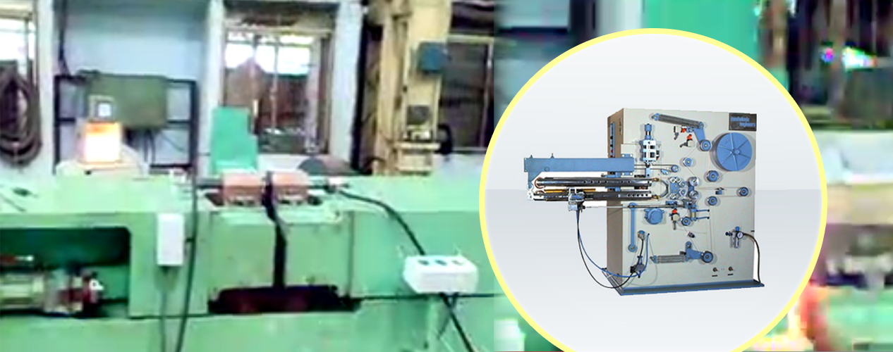
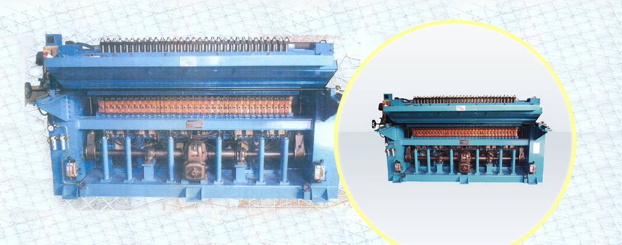
Wire Mesh Welding Machine
Wire mesh welder is designed for economical manufacture of welded steel wire fabric for general use, confirming to I.S. Specification 1566/4948 as per the welding range specified. The wires for the mesh can be cold drawn or can be galvanized steel wires. However they should be clean and without any rust and oil.
The construction permits the longitudinal wires to be fed directly from spools, automatically pulled as the fabric progresses whereas cross wires cut to length, straightened and fed into longitudinal wires during welding. It is advisable that customer provide a five roller straightener cum stand for proper feeding of long wires.
Construction:
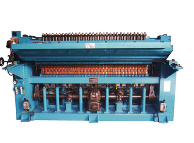
Frame:
The main frame of machine is of welded steel construction suitably straightened at various places. It is stress relieved after welding so as to maintain its alignment.
Transformer:
The main frame supports a battery of transformers connected suitably over three phases of power supply for balanced loading and maximum utilization of power. These transformers are housed in lower portion of the frame above the drive system.
Transformers are connected in group on primary side and secondaries are arranged in segments over the width of the machine. Bottom electrodes are mounted directly on the bus bars and are movable in ‘T’ slots for adjustment of pitch across the width. Electrodes are connected alternatively to two ends of secondary pressure head. Top electrodes serve the purpose of shorting the the neighbouring bottom electrodes These are connected to pressure heads which are mounted on top beam. The top beam slides up and down continuously in its guide, pressing the electrodes on bottom electrodes through spring, thus squeezing the wire between top and bottom electrodes. The pressure on wire adjusted by adjusting the compression of springs.
Drive System:
Drive system incorporates motor, brake, worm gear reducer and eccentric drive. There are two sets of eccentric one with fixed stroke drive top beam and the other with variable stroke moving horizontal slide for feeding of live wires through linkage mechanism. The stoke of the eccentric is adjusted as per the pitch of cross wires.
Line wire Feeding:
This consists of a slide on which number of unidirectional clutches/collets is fixed. These collets pull the line wire as the slide moves forward. There are other equal numbers of collets mounted on a fixed platen, which holds the wire in position as the moving collets move backward. These collets are adjusted as per pitch of the line wire. A single collet accommodates a range of diameters of wires.
Cross wire feeder:
Cross wire cut to length and straightened are put in hopper. They are automatically fed between the electrodes by a feeding bar which is operated by a pneumatic actuator. Every time the actuator is operated a single cross wire is picked up dropped between the electrodes. The dropped wire is held in the position by electromagnets which are pre-aligned with respect to the line wires.
The feeder is adjustable for various diameters of cross wires. The signal for feeding a wire is taken from a limit switch operated by top beam.
Control System:
The machine is provided with synchronous solid state electronic control circuit consisting of squeeze timer, heat control card and thyristor firing systems. These pairs of thyristors are used for three phases controlling three sets of welding transformers. The initiation of firing is done by actuating a proximity switch during the operation of top beam automatically. The control provides squeeze and weld timer from 1 to 99 cycles.
The main motor speed is controlled with help of variable A.C. motor controller. An instantaneous breaking control is also provided for emergency as well on fault conditions.
Cooling System:
All bus bars, transformers and thyristors are water cooled by continuously running water through passages provided. |