Brake Shoe Welding Machine
 |
| Technical Data |
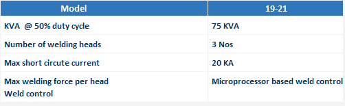 |
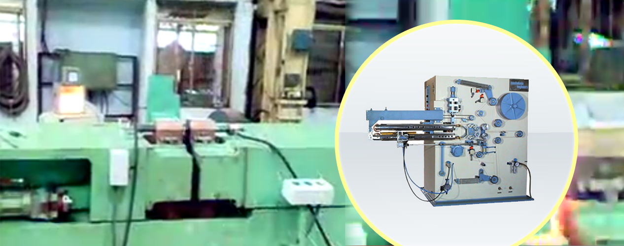
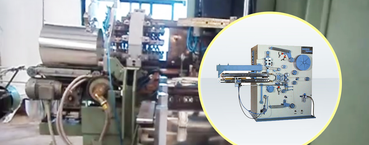
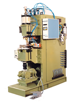
Brake Shoe Welding Machine This special purpose projection Welding Machine is specially designed for welding brake shoe assemblies. The machine is equipped with basic welding Transformer, Microprocessor based control, pneumatically actuated vertical welding head and special rotary indexing fixture with drives etc. The general layout of the machine is as shown in figure enclosed. Operation: In case foot-press continues to be pressed, the weld schedule is repeated. This continues as long as the foot-switch depressed. Each rotary table carries two fixtures. Hence one fixture is free for loading/ unloading when the other is being welded. It is feasible for the operator to keep the machine in continues operation whilst loading/unloading the fixtures(electrodes) sequentially. The ‘OFF TIME’ setting in the weld schedule can be used to control the cycle time without hampering weld quality and to suit operator convenience. Constuction: Welding Transformer: Current Conrol by Transformer Taps: Weldor Control: Cooling Systems: The transformer, electrodes and thyristors are water cooled and discharge to an open drain pot for visual observation of flow. Electrode Control System: Vertical electrodes are actuated by a heavy duty adjustable stroke pneumatic cylinder. The cylinder is operated by a solenoid valve by the weld control. Compressed air at 2 kg/sqcm to 7 kg/sqcm acting through the pneumatic cylinder provides the electrodes force. Machine is provided with air filters, regulators with guage, lubricators etc. together with internal air connections. Adjustment of Weldign Force: The welding force is adjusted by setting the air pressure with the help of regulator. Forge function is also settable by proper selection of the parameters in the control. |
Note: As efforts are constantly being made to improve both design and methods of manufacture, machine supplied may differ in details from illustrations and specification given. |


